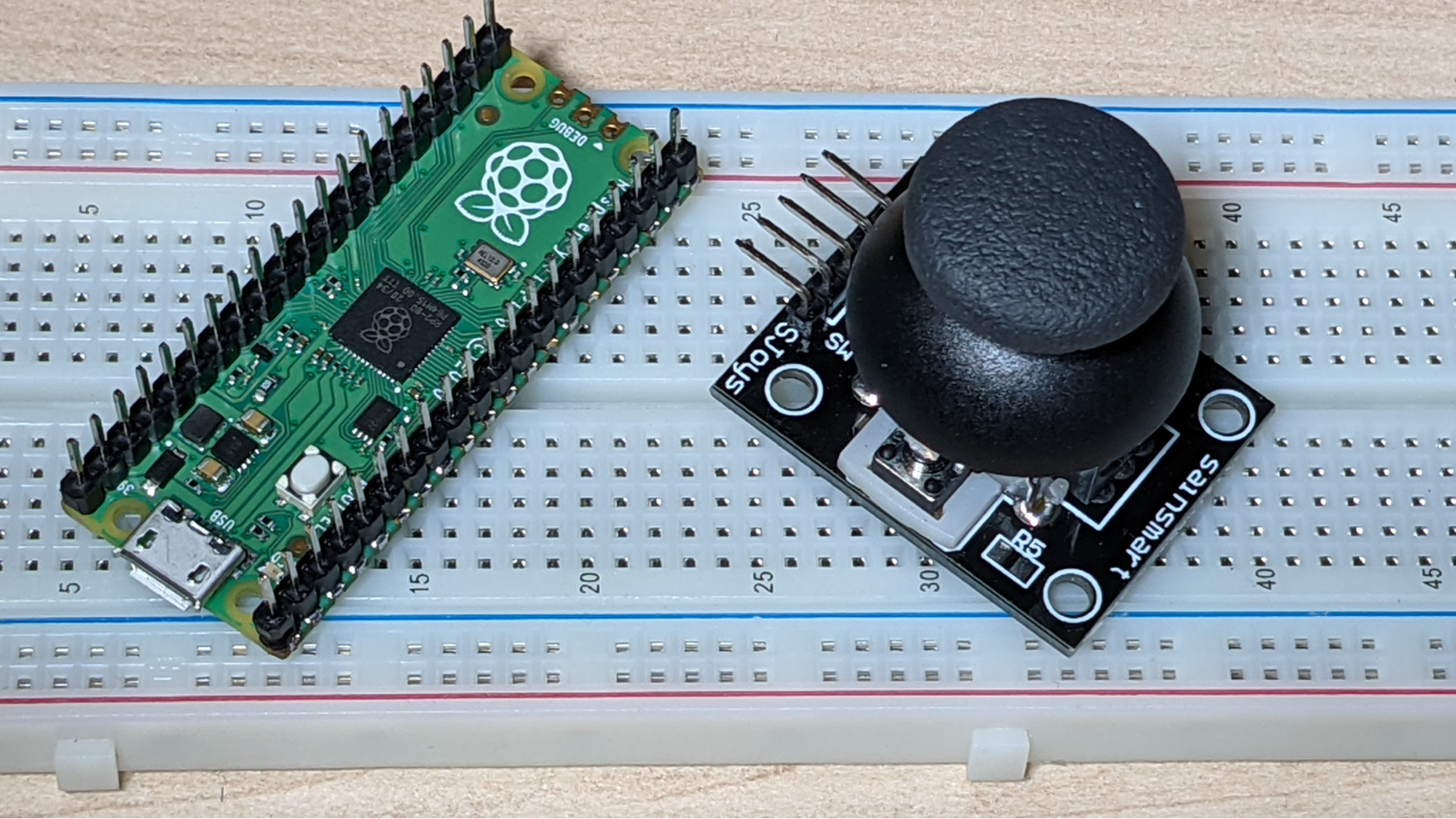
There are many reasons you might want to use an analog joystick in your Raspberry Pi Pico project. Perhaps you’re creating a game or maybe you need an input device for navigating. Whatever the case, connecting an analog stick to your Raspberry Pi Pico is really easy and coding for it in MicroPython is also a snap.
What you’ll need
- Raspberry Pi Pico with pins. See how to solder pins to Raspberry Pi Pico.
- Analog thumb joystick with 5-pin interface. There are many models. We used one of these.
- Breadboard (optional). You can also connect your joystick directly to the pins.
- Five jumper cables: female-to-male. If you’re not using a breadboard, you’ll need female-to-female.
If you haven’t programmed your Pico before, see our tutorial on how to set up Raspberry Pi Pico.
Wiring a Joystick to Raspberry Pi Pico
1. Wire the joystick’s 5 pins to the Pico as follows:
- GND to GND (physical pin 38)
- +5V to 3V3 Out (physical pin 36). Yes, a 5V joystick will work with the 3V3 power of Pico.
- VRx to GP27 / ADC1 (physical pin 32)
- VRy to GP26 / ADC0 (physical pin 31)
- SW to GP16 (physical pin 21). This would work with most of the GPI pins.
Coding a Joystick in MicroPython for Raspberry Pi Pico
An analog thumbstick is effectively three devices in one: a potentiometer for the X axis, a potentiometer for the Y axis and a digital momentary button when you press down. Below, we’ll write some simple code to help us see where the joystick is pointing.
2. Start a blank program in your MicroPython IDE, most likely Thonny.
3. Import the necessary modules: Pin, ADC from machine and utime
from machine import Pin, ADC
import utime
We’ll use the utime.sleep function later to put a necessary delay into a loop which reads the button state.
4. Create xAxis and yAxis variables and assign them to the GP pins for each, 27 and 26.
xAxis = ADC(Pin(27))
yAxis = ADC(Pin(26))
5. Create a button variable and assign it to a Pin object.
button = Pin(16,Pin.IN, Pin.PULL_UP)Note that the Pin object has three arguments, the GP number, the mode (which is input in our case) and whether it has a pull-up or pull-down resistor. We want it to be in input mode and pull up.
6. Create a continuous loop that checks and prints values for x, y and button.
while True:
    xValue = xAxis.read_u16()
    yValue = yAxis.read_u16()
    buttonValue= button.value()
    print(str(xValue) +", " + str(yValue) + " -- " + str(buttonValue))
    utime.sleep(0.1)
7. Run the code and observe the results in the MicroPython shell as you move the joystick and press the button. What you’ll likely see is that, if the joystick isn’t moved or pressed, the X and Y values will be around 32,000 to 33,000 and the button value will be 1. Moving to the left will put the X value in the 300 to 500 range and to the right will be around 65,000. Pointing up will put the 300 to 500 range and pointing down will be around 65,000. Pressing the button will give it a value of 0 while you hold it down.
8. Stop the execution and erase the print statement to save space.
9. Create variables for the plain English status of X, Y and button. Place them within the loop and give them default values that an untouched joystick.
    xStatus = "middle"
    yStatus = "middle"
    buttonStatus = "not pressed"
10. Use if / then statements to correctly label the joystick and button status within the loop.
 if xValue <= 600:
        xStatus = "left"
    elif xValue >= 60000:
        xStatus = "right"
    if yValue <= 600:
        yStatus = "up"
    elif yValue >= 60000:
        yStatus = "down"
    if buttonValue == 0:
        buttonStatus = "pressed"
11. Use a print statement to print the variables and place it above the sleep command.
print("X: " + xStatus + ", Y: " + yStatus + " -- button " + buttonStatus)
Your final code should look like this:
xAxis = ADC(Pin(27))
yAxis = ADC(Pin(26))
button = Pin(16,Pin.IN, Pin.PULL_UP)

while True:
    xValue = xAxis.read_u16()
    yValue = yAxis.read_u16()
    buttonValue = button.value()
    xStatus = "middle"
    yStatus = "middle"
    buttonStatus = "not pressed"
    if xValue <= 600:
        xStatus = "left"
    elif xValue >= 60000:
        xStatus = "right"
    if yValue <= 600:
        yStatus = "up"
    elif yValue >= 60000:
        yStatus = "down"
    if buttonValue == 0:
        buttonStatus = "pressed"
    print("X: " + xStatus + ", Y: " + yStatus + " -- button " + buttonStatus)
    utime.sleep(0.1)
Now that you know how to identify what your joystick is doing, you can incorporate it into your MicroPython programs for Raspberry Pi Pico. See our list of Raspberry Pi Pico tutorials for more ideas.
