CircuitPython is a programming language designed to simplify experimenting with low cost boards, typically microcontroller boards made by Adafruit. CircuitPython can also be used on the Raspberry Pi and via two projects we introduce how to use CircuitPython with the Raspberry Pi. The first project is the humble LED, controlling how to blink an LED enables us to understand how we communicate and control components. The second project involves using additional components connected to the GPIO via a jumper wire to Stemma QT connector.
CircuitPython on the Raspberry Pi is transferable to other devices, such as Adafruit’s QT Py RP2040, Feather RP2040 and Pimoroni’s Keybow 2040, along with the Raspberry Pi Pico. So the skills learned here are applicable to any board that can run CircuitPython
For This Project You Will Need
- Any model of Raspberry Pi, but for best results use a 3 / 4
- The latest Raspberry Pi OS
Project 1
- A breadboard
- LED
- 330 Ohm Resistor (Orange-Orange-Brown-Gold)
- 2x male to female jumper wires
Project 2
- Adafruit MPR121 Capacitive Touch Sensor
- 4x female to female jumper wires
- 2x crocodile clips
- 2x fruit
- StemmaQT to breadboard leads
Installing CircuitPython
1. Open a terminal and update, then upgrade the software on your Raspberry Pi.
$ sudo apt update
$ sudo apt upgrade
2. Upgrade setuptools, a Python toolkit to manage Python package installations.
$ sudo pip3 install --upgrade setuptools
3. Change directory to your home directory and then use pip3 to install Adafruit’s Python Shell tool. The command “cd ~” is shorthand for the home directory.
cd ~
$ sudo pip3 install --upgrade adafruit-python-shell
4. Download Adafruit’s installation script and then run the script to configure CircuitPython. During the installation it may state that you are using Python 2, it will prompt you to update, this is safe to say Yes to.
$ wget https://raw.githubusercontent.com/adafruit/Raspberry-Pi-Installer-Scripts/master/raspi-blinka.py
$ sudo python3 raspi-blinka.py
Blinking an LED
The humble flashing LED is always the first test for a new electronics project. It enables us to be certain that our code is working and that our wiring is sound. For this project we shall wire up an LED to GPIO 17 via two jumper wires and a 330 Ohm resistor. The wiring for this project looks as follows.
1. Open the Thonny editor and import three libraries of code. The first is “time” and this is used to control the pace of our code. The next two, “board” and “digitalio” are CircuitPython specific libraries. Board enables us to interact with the GPIO, digitalio is used to control the state of a GPIO pin.
import time
import board
import digitalio
2. Using an object, led, we tell CircuitPython which GPIO pin we are using, and that it is an output. Our LED is connected to GPIO 17, which in CircuitPython is board.D17.
led = digitalio.DigitalInOut(board.D17)
led.direction = digitalio.Direction.OUTPUT
3. Create a while True loop which will turn the LED on (led.value = True) and off (led.value = False) every 0.1 seconds.
while True:
    led.value = True
    time.sleep(0.1)
    led.value = False
    time.sleep(0.1)
Your code should look like this
import time
import board
import digitalio

led = digitalio.DigitalInOut(board.D17)
led.direction = digitalio.Direction.OUTPUT

while True:
    led.value = True
    time.sleep(0.1)
    led.value = False
    time.sleep(0.1)
Save the code and click Run to start it. The LED should now flash on and off every 0.1 seconds. With the test complete we can move on to Project 2.
Using a Capacitive Touch Sensor With CircuitPython
The next project requires a little more equipment, but it is no more difficult than controlling an LED. In this project we shall use an MPR121 capacitive touch sensor and a few crocodile clips to enable us to use conductive objects as inputs.
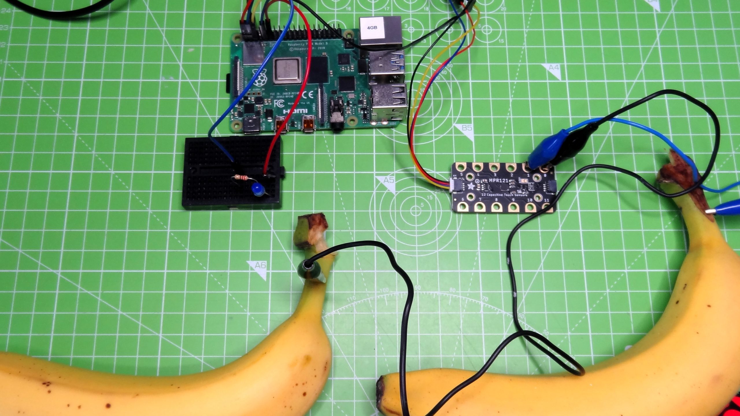
The MPR121 is designed for microcontroller boards that have a Stemma QT connector, but with a little ingenuity we can make it work on a Raspberry Pi. The classic MPR121 example project is a banana piano, where touching a banana triggers a note to be played. For our simplified version, we will have two pieces of fruit, and each will turn the LED from the previous project, on and off.
To use the MPR121 touch sensor we will need to install an additional piece of software. Open a terminal and enter the following command.
$ sudo pip3 install adafruit-circuitpython-mpr121The MPR121 board uses a StemmaQT connector, to use with a Raspberry Pi we need to use the breakout lead that gives us four jumper wires. They are colour coded as follows. Red to 3V, Black to GND, Yellow to SCL (GPIO3) and Blue to SDA (GPIO2). Connect the MPR121 to the Raspberry Pi using female to female jumper wires.
Using crocodile clips, connect a banana to input 0 of the MPR121, attach the other banana to input 1. Any conductive objects will work, aluminium foil and card is a cheap and easy way to make fun touch interfaces.
Open Thonny and create a new file.
1. Import the three libraries of code. The first is “time” and this is used to control the pace of our code. The next two, “board” and “digitalio” are CircuitPython specific libraries. Board enables us to interact with the GPIO, digitalio is used to control the state of a GPIO pin.
import time
import board
import digitalio
2. Import two extra libraries for use with the MPR121 The first “busio” enables our code to access the I2C interface that the MPR121 uses for communication. The second clearly enables the use of the MPR121 in our code.
import busio
import adafruit_mpr121
3. Using an object, led, we tell CircuitPython which GPIO pin we are using, and that it is an output. Our LED is connected to GPIO 17, which in CircuitPython is board.D17.
led = digitalio.DigitalInOut(board.D17)
led.direction = digitalio.Direction.OUTPUT
4. Create an object, i2c, that contains the GPIO pins that are used to connect the MPR121 via I2C. Then connect to the MPR121. CircuitPython has two references for the SCL (clock) and SDA (data) pins used in I2C. These references use the default pins for I2C no matter the device. So using these references on a Raspberry Pi, QT Py RP2040 and Raspberry Pi Pico all use the default I2C pins.
i2c = busio.I2C(board.SCL, board.SDA)
mpr121 = adafruit_mpr121.MPR121(i2c)
5. Create a loop that will continually check the status of input 0, connected to a banana. If the banana is the function will return True, and then the code to print a message to the Python Shell and turn the LED on (led.value = True) will activate.
while True:
    if mpr121.is_touched(0) ==  True:
        print("This banana turns light on")
        led.value = True
6. Enter a second check to read the status of input 1 which is connected to the banana used to turn off the LED. If this is pressed the function returns True and triggers the code to print a message to the Python Shell and to turn the LED off.
 elif mpr121.is_touched(1) == True:
        print("This banana turns the light off")
        led.value = False
    time.sleep(0.5)
With the code complete we can save the file as touch-test.py and click on Run to start the code. Now press the bananas to turn the LED on and off.
Your code should look like this
import time
import board
import digitalio
import busio
import adafruit_mpr121

led = digitalio.DigitalInOut(board.D17)
led.direction = digitalio.Direction.OUTPUT
i2c = busio.I2C(board.SCL, board.SDA)
mpr121 = adafruit_mpr121.MPR121(i2c)

while True:
    if mpr121.is_touched(0) ==  True:
        print("This banana turns light on")
        led.value = True
    elif mpr121.is_touched(1) == True:
        print("This banana turns the light off")
        led.value = False
    time.sleep(0.5)
CircuitPython provides the easiest way to get started on a project, thanks to a large community of makers using the language and creating libraries for components. CircuitPython is available for over 200 boards, and despite only being with us since 2018, it has been the base of many projects.
This article originally appeared in an issue of Linux Format magazine.