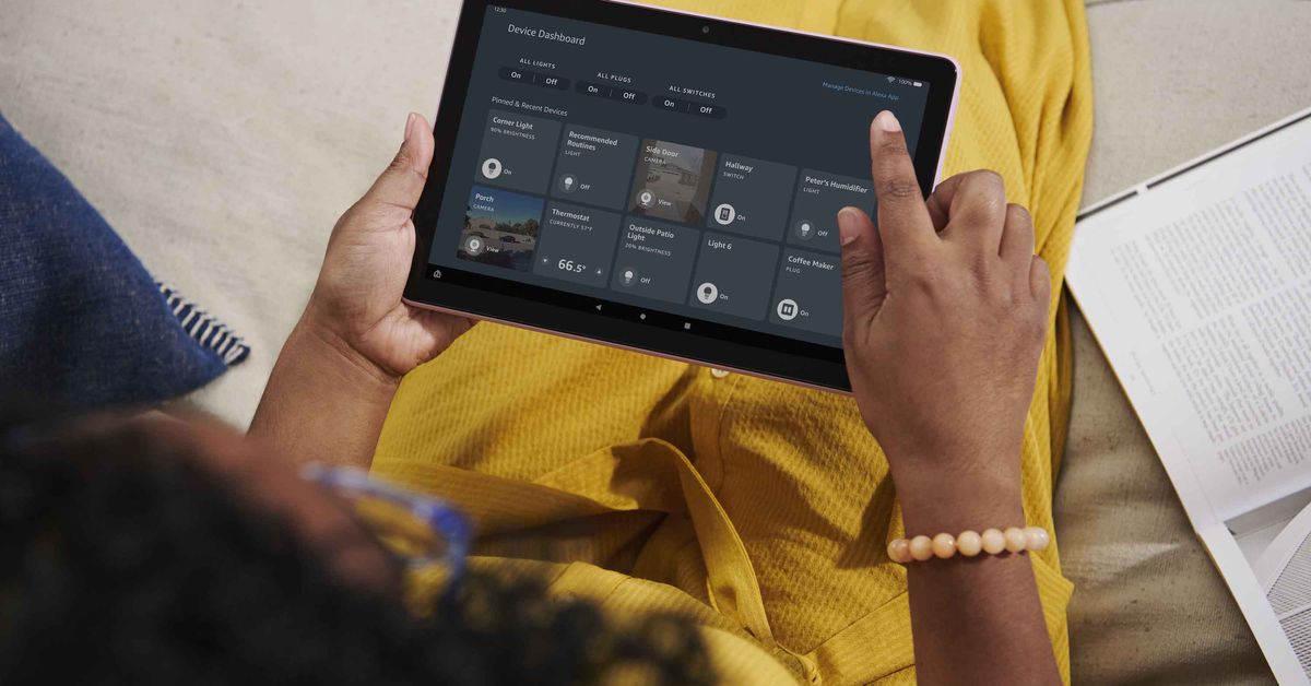
Amazon is overhauling its tablet lineup today with new Fire HD 10 models alongside refreshed options for kids.
The $149.99 Fire HD 10 now looks much more in line with what you’d expect from a modern tablet, with a thinner design and slimmed-down bezels on all four sides. The RAM has been boosted by 50 percent to 3GB, and Amazon says the 1080p screen is brighter than before. It runs on what Amazon describes as a “powerful octa-core processor,” though it’s unclear what — if any — improvement this represents over the 2Ghz octa-core chip that failed to impress us in the last model.
Speaking of performance, Amazon is also introducing its “most powerful 10-inch tablet ever,” the Fire HD 10 Plus. This model has 4GB of RAM, a soft touch finish, and wireless charging, though again Amazon isn’t giving details on the processor. Like the Fire HD 8 Plus, there’s an optional made-for-Amazon wireless charging dock, this time made by Anker. The HD 10 Plus costs $30 more than the non-Plus model, at $179.99.
The Fire HD 10 Plus with keyboard case.
Amazon’s tablets aren’t normally associated with productivity, but the company is making a go of it with the new Fire HD 10 range. The tablets will be available in “Productivity Bundles” including Fintie-designed keyboard cases and a one-year subscription to Microsoft 365; the bundles start at $219.99 and the keyboards will cost $49.99 as standalone purchases. Amazon has also added a new split-screen multitasking feature to Fire OS.
As for the kids lineup, Amazon is introducing a whole new range of tablets called Fire Kids Pro. (Clearly, only the most professional kids need apply.) Available in 7-inch ($99.99), 8-inch ($139.99), and 10-inch ($199.99) versions, the Fire Kids Pro tablets have slim protective cases with built-in kickstands.
The Fire HD 10 Kids Pro.
Amazon says the Kids Pro’s home screen “looks and feels more like a ‘grown-up’ tablet,” and the browser has an option to provide “open but filtered” web access, with parents able to block or allow specific sites. There’s also an app store where kids are able to request app downloads that parents can approve later, and the tablets come with a year of Amazon’s Kids+ service for educational and entertainment content.
Amazon is also releasing a Kids Edition of the new Fire HD 10, which includes a “kid-proof” case, a two-year replacement warranty, and a year of Amazon Kids+. This model will sell for $199.99, and at launch Amazon is offering a 30-percent discount if you buy two of them.
All of Amazon’s new tablets will start shipping on May 26th.
CircuitPython is a programming language designed to simplify experimenting with low cost boards, typically microcontroller boards made by Adafruit. CircuitPython can also be used on the Raspberry Pi and via two projects we introduce how to use CircuitPython with the Raspberry Pi. The first project is the humble LED, controlling how to blink an LED enables us to understand how we communicate and control components. The second project involves using additional components connected to the GPIO via a jumper wire to Stemma QT connector.
CircuitPython on the Raspberry Pi is transferable to other devices, such as Adafruit’s QT Py RP2040, Feather RP2040 and Pimoroni’s Keybow 2040, along with the Raspberry Pi Pico. So the skills learned here are applicable to any board that can run CircuitPython
For This Project You Will Need
Any model of Raspberry Pi, but for best results use a 3 / 4
The latest Raspberry Pi OS
Project 1
A breadboard
LED
330 Ohm Resistor (Orange-Orange-Brown-Gold)
2x male to female jumper wires
Project 2
Adafruit MPR121 Capacitive Touch Sensor
4x female to female jumper wires
2x crocodile clips
2x fruit
StemmaQT to breadboard leads
Installing CircuitPython
1. Open a terminal and update, then upgrade the software on your Raspberry Pi.
$ sudo apt update
$ sudo apt upgrade
2. Upgrade setuptools, a Python toolkit to manage Python package installations.
$ sudo pip3 install --upgrade setuptools
3. Change directory to your home directory and then use pip3 to install Adafruit’s Python Shell tool. The command “cd ~” is shorthand for the home directory.
cd ~
$ sudo pip3 install --upgrade adafruit-python-shell
4. Download Adafruit’s installation script and then run the script to configure CircuitPython. During the installation it may state that you are using Python 2, it will prompt you to update, this is safe to say Yes to.
The humble flashing LED is always the first test for a new electronics project. It enables us to be certain that our code is working and that our wiring is sound. For this project we shall wire up an LED to GPIO 17 via two jumper wires and a 330 Ohm resistor. The wiring for this project looks as follows.
1. Open the Thonny editor and import three libraries of code. The first is “time” and this is used to control the pace of our code. The next two, “board” and “digitalio” are CircuitPython specific libraries. Board enables us to interact with the GPIO, digitalio is used to control the state of a GPIO pin.
import time
import board
import digitalio
2. Using an object, led, we tell CircuitPython which GPIO pin we are using, and that it is an output. Our LED is connected to GPIO 17, which in CircuitPython is board.D17.
led = digitalio.DigitalInOut(board.D17)
led.direction = digitalio.Direction.OUTPUT
3. Create a while True loop which will turn the LED on (led.value = True) and off (led.value = False) every 0.1 seconds.
while True:
    led.value = True
    time.sleep(0.1)
    led.value = False
    time.sleep(0.1)
Your code should look like this
import time
import board
import digitalio

led = digitalio.DigitalInOut(board.D17)
led.direction = digitalio.Direction.OUTPUT

while True:
    led.value = True
    time.sleep(0.1)
    led.value = False
    time.sleep(0.1)
Save the code and click Run to start it. The LED should now flash on and off every 0.1 seconds. With the test complete we can move on to Project 2.
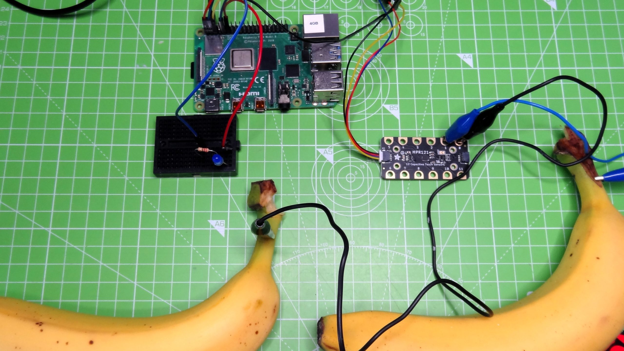
Using a Capacitive Touch Sensor With CircuitPython
(Image credit: Tom’s Hardware)
The next project requires a little more equipment, but it is no more difficult than controlling an LED. In this project we shall use an MPR121 capacitive touch sensor and a few crocodile clips to enable us to use conductive objects as inputs.
The MPR121 is designed for microcontroller boards that have a Stemma QT connector, but with a little ingenuity we can make it work on a Raspberry Pi. The classic MPR121 example project is a banana piano, where touching a banana triggers a note to be played. For our simplified version, we will have two pieces of fruit, and each will turn the LED from the previous project, on and off.
To use the MPR121 touch sensor we will need to install an additional piece of software. Open a terminal and enter the following command.
$ sudo pip3 install adafruit-circuitpython-mpr121
(Image credit: Tom’s Hardware)
The MPR121 board uses a StemmaQT connector, to use with a Raspberry Pi we need to use the breakout lead that gives us four jumper wires. They are colour coded as follows. Red to 3V, Black to GND, Yellow to SCL (GPIO3) and Blue to SDA (GPIO2). Connect the MPR121 to the Raspberry Pi using female to female jumper wires.
(Image credit: Tom’s Hardware)
Using crocodile clips, connect a banana to input 0 of the MPR121, attach the other banana to input 1. Any conductive objects will work, aluminium foil and card is a cheap and easy way to make fun touch interfaces.
Open Thonny and create a new file.
1. Import the three libraries of code. The first is “time” and this is used to control the pace of our code. The next two, “board” and “digitalio” are CircuitPython specific libraries. Board enables us to interact with the GPIO, digitalio is used to control the state of a GPIO pin.
import time
import board
import digitalio
2. Import two extra libraries for use with the MPR121 The first “busio” enables our code to access the I2C interface that the MPR121 uses for communication. The second clearly enables the use of the MPR121 in our code.
import busio
import adafruit_mpr121
3. Using an object, led, we tell CircuitPython which GPIO pin we are using, and that it is an output. Our LED is connected to GPIO 17, which in CircuitPython is board.D17.
led = digitalio.DigitalInOut(board.D17)
led.direction = digitalio.Direction.OUTPUT
4. Create an object, i2c, that contains the GPIO pins that are used to connect the MPR121 via I2C. Then connect to the MPR121. CircuitPython has two references for the SCL (clock) and SDA (data) pins used in I2C. These references use the default pins for I2C no matter the device. So using these references on a Raspberry Pi, QT Py RP2040 and Raspberry Pi Pico all use the default I2C pins.
5. Create a loop that will continually check the status of input 0, connected to a banana. If the banana is the function will return True, and then the code to print a message to the Python Shell and turn the LED on (led.value = True) will activate.
while True:
    if mpr121.is_touched(0) ==  True:
        print("This banana turns light on")
        led.value = True
6. Enter a second check to read the status of input 1 which is connected to the banana used to turn off the LED. If this is pressed the function returns True and triggers the code to print a message to the Python Shell and to turn the LED off.
CircuitPython provides the easiest way to get started on a project, thanks to a large community of makers using the language and creating libraries for components. CircuitPython is available for over 200 boards, and despite only being with us since 2018, it has been the base of many projects.
This article originally appeared in an issue of Linux Format magazine.
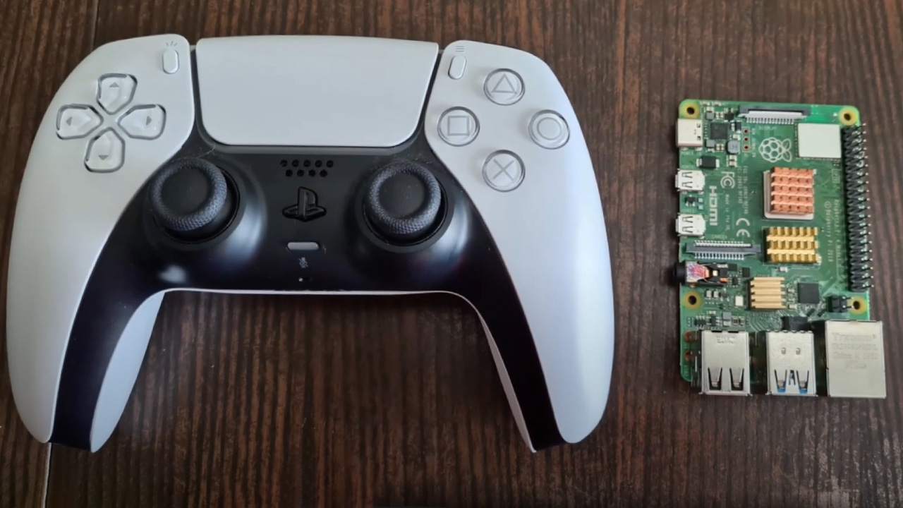
Being able to play your PlayStation 4 and 5 games all around your house via Remote Play streaming is a neat feature, but the small number of officially supported devices means you’re stuck with Windows, macOS, iOS, Android, or another PlayStation. Enterprising coders determined to get an open-source Remote Play client running on a wider selection of devices have had it happily streaming on Linux for a while, and the humble Raspberry Pi, with its Debian-based OS, is the latest target, as shown in this video from Philippines-based Evoneg Tech.
To get it going you’ll need a Raspberry Pi 4, and a fork of the Chiaki streaming app from Github. Remote Play needs to be activated on your PS5, and you should pair a Bluetooth controller with your Pi (a DualShock will work fine, but make sure it’s not still paired with, and within range of, your console).
You’ll need to install a few dependencies first, then build the app on your Pi, so don’t jump in unless you’re comfortable with typing console commands. There’s a full guide to Pi installation on the project’s Github wiki. You’ll also need your PSN account ID, which can be extracted by following the steps here.
It works on both wired and wireless connections, and with a good connection you’ll get a 1080p/60fps connection. The devs say it also works on the PS4 Pro, but there’s no mention of the original PS4 console. Nintendo Switch owners should note that there’s a build of the app for their console too, but it has some very specific installation instructions.
If you buy something from a Verge link, Vox Media may earn a commission. See our ethics statement.
If a $100 budget phone is the fast-food dollar menu and a $1,000 flagship is a steakhouse dinner, then the Samsung Galaxy A52 5G sits comfortably halfway between the two: the laid-back all-day cafe with surprisingly tasty food.
It’s good. More importantly, it’s good where it matters. Sure, you have to order your food at the counter and get your own water refills, but it’s worth it because brunch is fantastic and the prices are reasonable.
The A52 5G is the highest-specced of the budget A-series Galaxy phones we’ll see in the US this year, offering all of the basics for its $499 price tag along with a few good extras. Its 6.5-inch screen comes with a fast 120Hz refresh rate that’s scarce at this price point. Its main camera includes optical image stabilization, something I missed when I used the more expensive OnePlus 9. The A52 5G is rated IP67 waterproof for some extra peace of mind. And hey, there’s still a headphone jack! In this economy!
Still, this isn’t a flagship, and costs had to be cut somewhere. The device’s frame and back panel are plastic, and while I like the matte finish on the back, there’s a certain hollowness when you tap on it that’s not very reassuring. There’s also no telephoto to complement the wide and ultrawide cameras, just digital zoom plus a depth sensor and macro camera of dubious usefulness.
The important stuff is here, though. Samsung has the A52 5G on its list for monthly OS updates currently, and it says it will offer three years of major Android OS updates and at least some security support for four years. That will go a long way toward making the most out of your investment in this phone, and it will help you take advantage of its headline feature: 5G — Sub-6GHz, specifically, with hardware-level support for the C-band frequencies carriers will start using in 2022.
It’s getting more common to see 5G offered in midrange and budget phones, but in this country, it’ll be a couple more years before our 5G networks are truly good. Healthy device support for the next few years makes it more likely that the A52 5G will actually last long enough to make it to that 5G promised land.
The A52 5G offers solid everyday performance with a Snapdragon 750G chipset and 6GB of RAM.
Samsung Galaxy A52 5G performance and screen
The A52 5G uses a Snapdragon 750G processor with 6GB of RAM, and the combination feels like a good fit here. You can certainly push it out of its comfort zone with heavier tasks like webpages with JavaScript, and I noticed it hesitating a moment too long when opening the camera app from the lock screen. But for day-to-day tasks and social media scrolling, it keeps up well.
As in last year’s model, the screen is where the A52 5G (and Samsung generally) really stand out. This is a 6.5-inch 1080p OLED panel that’s rich, bright, and generally lovely to look at. Plus, it offers all of the velvety smoothness that comes with its 120Hz refresh rate. Swiping between home screens, opening apps, scrolling through Twitter — it all just feels nicer with a fast refresh rate.
Even considering the additional power needed for the 120Hz screen, the A52 5G’s 4,500mAh battery consistently lasted well into the next day in my use. I managed to get two full days out of it when I forgot to charge it overnight and decided to embrace chaos and just plow through on the remaining charge. This was with light to moderate use, and I was down to low double-digit battery percentage by the end of day two, but my gamble paid off.
One feature I continue to fight a losing battle with on the A52 5G is the in-display optical fingerprint sensor. I’ve been chastised by the phone many times for not leaving my finger on the sensor long enough, and I almost always need at least two tries to get it to register. That hit rate goes down significantly outside in bright light.
These problems aren’t unique to this device, and you can just opt to use (less secure) facial recognition or a plain old PIN to lock and unlock the phone. But there are nicer in-display fingerprint readers in pricier phones like the OnePlus 9 and Samsung’s own S21, so it’s a trade-off to be aware of.
The Galaxy A52 5G ships with Android 11, which is great. The less good news is, as we saw in the S21 devices earlier this year, Samsung’s latest take on the OS stuffs a lot of unwanted apps, ads, and general clutter into the UI. I see enough ads throughout my day as it is, and I do not appreciate seeing one more when I check the weather on my phone’s own weather app.
If there’s a positive way to look at this situation, it’s that it feels more forgivable on a budget phone than on a $1,000-plus flagship. But I’d rather not have the ads at all. If you buy the similarly priced Pixel 4A 5G, you give up a lot of other features from the A52 5G, but you get an ad-free experience.
Housed in the rear camera bump are a standard wide, ultrawide, macro, and depth sensor.
Samsung Galaxy A52 5G camera
The A52 5G includes three rear cameras, plus a 5-megapixel depth sensor. You get a 64-megapixel standard wide with OIS, 12-megapixel ultrawide, and the seemingly obligatory 5-megapixel macro camera. There’s also a front-facing 32-megapixel selfie camera.
Taken with 2x digital zoom
Taken with ultrawide
Taken with ultrawide
The 64-megapixel main camera produces 16-megapixel images in its standard photo mode that are bright with the very saturated colors you’d expect from a Samsung phone. Sometimes the look is pleasant, but more often than not, it’s a little much for my taste. The good news is that this sensor is capable of capturing lots of fine detail in good lighting, and it even does well in dim to very low-light conditions.
I put its night mode up against the Google Pixel 4A, which is still the low-light champ in the midrange class. There’s more noise visible in the A52 5G’s night mode shot, and details have a watercolory look, but while the 4A hangs on to its title, the A52 5G is quite close behind.
Left: Galaxy A52 night mode. Right: Pixel 4A night mode.“,”image_left”:{“ratio”:”*”,”original_url”:”https://cdn.vox-cdn.com/uploads/chorus_asset/file/22465175/samsung_night_crop.jpg”,”network”:”verge”,”bgcolor”:”white”,”pinterest_enabled”:false,”caption”:null,”credit”:null,”focal_area”:{“top_left_x”:0,”top_left_y”:0,”bottom_right_x”:2040,”bottom_right_y”:1580},”bounds”:[0,0,2040,1580],”uploaded_size”:{“width”:2040,”height”:1580},”focal_point”:null,”asset_id”:22465175,”asset_credit”:null,”alt_text”:””},”image_right”:{“ratio”:”*”,”original_url”:”https://cdn.vox-cdn.com/uploads/chorus_asset/file/22465178/pixel_night_crop.jpg”,”network”:”verge”,”bgcolor”:”white”,”pinterest_enabled”:false,”caption”:null,”credit”:null,”focal_area”:{“top_left_x”:0,”top_left_y”:0,”bottom_right_x”:2040,”bottom_right_y”:1580},”bounds”:[0,0,2040,1580],”uploaded_size”:{“width”:2040,”height”:1580},”focal_point”:null,”asset_id”:22465178,”asset_credit”:null,”alt_text”:””},”credit”:null}” data-cid=”apps/imageslider-1619271003_9454_116978″>
Left: Galaxy A52 night mode. Right: Pixel 4A night mode.
The Pixel 4A is still the better camera in good lighting, too, but the differences are more subjective here. The 4A goes for more subdued color rendering, and the A52 5G’s images lack a little contrast in comparison.
So the A52 5G can’t beat the generation-old imaging tech in the 4A, but that might say more about the Pixel than anything else. Aside from that, the A52 5G turns in good all-around camera performance. Images from the ultrawide sometimes have a little cooler color cast but are generally good. The selfie camera offers two zoom settings: a slightly cropped-in standard wide view and an ever-so-slightly wider angle. The “focal length” difference between the two is almost laughably small.
At its default settings, the selfie camera does a fair amount of face smoothing and brightening. I don’t think it quite crosses the line into hamcam territory, but it certainly has that telltale “maybe it’s AI, maybe it’s Maybelline” smoothed look to it.
If you want to go full hamcam, there’s a new mode just labeled “fun” in the camera app with AR face filters brought to you by Snapchat. There’s a different selection of them every day, and you don’t need a Snapchat account to use or share them.
I’m tempted to dismiss them as “for the youths,” but maybe this is really for the olds like me who would rather not join another social platform if I can possibly avoid it, thank you very much. At last, I can transform my face into a piece of broccoli and share it with the world without logging in to Snapchat — three years after the kids have all moved on to something else. Anyway, it’s there, it works, and you can indeed turn your face into broccoli.
Good hardware and healthy software support make the A52 5G worth spending a little more on.
There’s a lot that the Galaxy A52 5G gets right. Maybe the most important feature is one that sounds much less exciting than cool headline specs: security updates for at least the next few years. At $500, this is the higher end of the budget market, but a few extra hundred dollars is likely easier to swallow if you know you’ll get a couple more years out of your investment.
Samsung has invested in hardware in all the right places: the 120Hz screen makes for an elevated user experience, battery life is good, camera performance is strong, and a healthy processor / chipset combination handles daily tasks well.
What I didn’t love — the cluttered software, fussy fingerprint sensor, a tendency toward oversaturated color in photos — feels more forgivable when the phone gets the nonnegotiable stuff right. The Pixel 4A 5G is probably this device’s closest competition, and it beats the A52 5G on camera quality and a cleaner UI, but it’s a smaller device without a fancy fast refresh rate screen. Depending on how you feel about either of those things, the 4A 5G might be the better pick for you.
In any case, the A52 5G is a good midrange phone today. But just as importantly, it will be a good phone a few years from now. With solid hardware and a software support system to back it up, this is a pricier budget phone that’s worth budgeting a little extra for.
If you buy something from a Verge link, Vox Media may earn a commission. See our ethics statement.
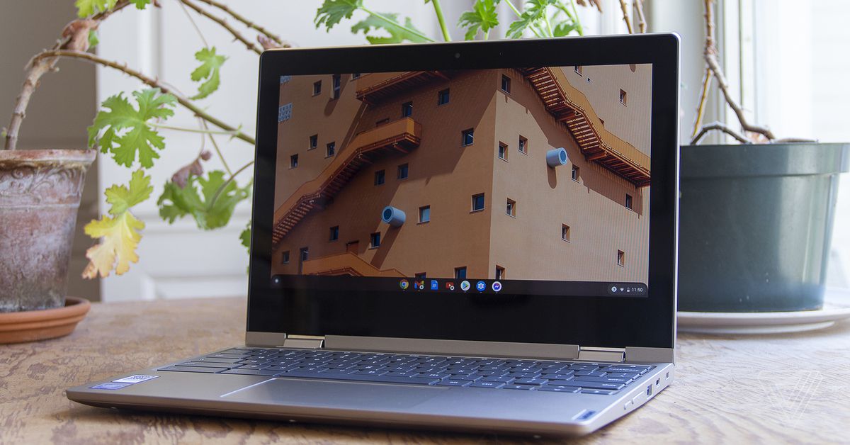
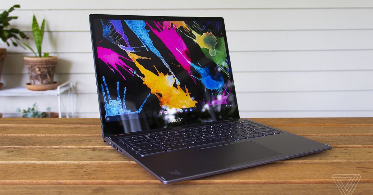
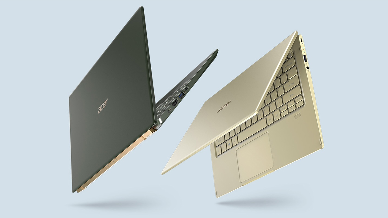
Lenovo’s Ideapad Flex 3 Chromebook is one of the tiniest Chromebooks I’ve ever used. It’s also one of the cheapest, retailing for just $349.99.
Any laptop that costs that little is going to have some serious drawbacks — and the Flex 3 certainly does. On the other hand, if you’re the sort of shopper who’s willing to set those aside, this little IdeaPad also has a number of pleasant surprises up its sleeve. There are even a few areas (in particular, the battery life) where it gives significantly more expensive devices a run for their money.
I’ll start with the pleasant surprises. The Flex 3 offers a more modern port selection than I’d expect at its price point — there are two USB 3.1 Type-C Gen 1 ports and two USB 3.1 Type-A Gen 1 ports (one on each side, which is really handy for charging and connecting accessories), as well as a microSD reader, an audio combo jack, and a lock slot. There’s a 720p webcam that works decently well if you’re not in low light. And the touchpad is surprisingly sturdy — I often find that touchpads in this price range feel plasticky. The Flex even comes with a Google Security H1 chip, which encrypts sensitive on-device data.
There’s a power button on the side, as well as a volume rocker.
There are two features that really impressed me (in addition to the battery life, which I’ll discuss later on). First, I can’t stop talking about the keyboard. It’s great, with tons of travel and a satisfying click. The keys have a slightly rough texture that really grew on me. I got one of the highest scores I’ve ever gotten on my usual typing test, with almost no errors. The only note is that it lacks backlighting, a feature you’ll find on more expensive devices like Acer’s Chromebook Spin 713 (our current top Chromebook pick) and Lenovo’s Flex 5 Chromebook.
God, I love a good keyboard.
Second, audio. The balance and volume that these 2W stereo speakers deliver are on par with those of any number of more expensive Chromebooks. They easily beat the Spin 713, which sounds tinny and thin. There are caveats, of course: There’s very little bass, percussion is weak, I heard a bit of distortion at max volume, and you’ll want an external speaker for any crowded setting. But the Flex is great for video conferences and regular music-listening, and certainly beats what I’ve heard from all kinds of Windows laptops that are over $1,000.
Now, for the major drawbacks. First, this thing is a clunker. It’s not too heavy, at 2.65 pounds, but it’s 0.7 inches thick, and it’s not too far from the size of many modern 13-inch laptops despite having just an 11-inch screen. My main turnoff, though, is the bezels. Good lord, the bezels are enormous. When I’m using the Flex 3, I feel like I’m looking at a small window of screen floating in an abyss of black. It looks like a device you’d have bought in 2014.
I wish Lenovo had sprung for a better screen.
I do like some things about the chassis, though. It doesn’t feel at all flimsy, with an aluminum cover and a non-plasticky finish. The display and keyboard are free of flex (despite the laptop’s name). And the 360 hinge is sturdy, with very little wobble.
Speaking of the display, though: That’s the second major drawback here. It’s cramped — I often use two windows side-by-side and I’ve been squinting at tiny text in order to make that work on the Flex 3. Moreover, it’s dim (maxing out at 250 nits), kicks back a ton of glare even indoors, and is quite low-resolution (1366 x 768). I’m gonna be real: It’s pixel-y to look at. I’ve been using the Flex 3 as my primary driver for a week, and while I will miss the keyboard and audio when I send it back, I can’t wait never to have to look at this terrible screen again.
That’s the lowdown on the chassis — let’s look inside. This Ideapad Flex 3 Chromebook configuration is powered by Intel’s dual-core Celeron N4020. That’s the bottom of the barrel as Intel processors go, and it comes with just 4GB of memory (LPDDR4-2400, soldered) and 64GB of eMMC 5.1 storage.
On a Windows machine, these specs would be a hard pass. But Chrome OS is a lighter load, and I can vouch that the Flex 3’s screen is a bigger limit on multitasking than its horsepower is. I was able to use the laptop for a substantial workload, jumping between dozens of Chrome tabs and some apps, but the experience was cramped enough that I wouldn’t recommend it.
The color is called “almond”.
Scrolling got a bit sluggish when I tried to work on top of a Spotify or YouTube stream, and the transitions between laptop and tablet mode were a bit slower than I would’ve liked. The only task where I ran into real trouble, though, was sorting through a batch of shots in Google Photos (with a couple other apps running on the side). The Flex 3 did get the job done, but it was quite slow. The one Zoom meeting I tried (on top of some other tabs I needed) was also a bad experience — audio randomly cut out a couple times, and video was stuttery throughout.
Overall, this device is best if you’re looking to do basic office or school tasks, and don’t think you’ll need to have more than a few things open at a time. (And in case this doesn’t go without saying, you’ll want to stay far away from this thing if you plan on doing anything fancy with Linux.)
The flipside of the weak processor is that the Flex 3 has excellent battery life. I averaged eight hours and 45 minutes to a charge with brightness at 50 percent — and I was pushing the thing harder than most people probably will be, as noted above. You can expect that this thing will last all day, and certainly longer than many more powerful Chromebooks. The 45W charger is acceptably quick, juicing the device up to 60 percent in 52 minutes.
Six rows of keys.
The Flex 3 runs Chrome OS, which means it can run Android apps natively. Some of these have improved since the last time I used this operating system — Messenger is now functional and no longer a complete disaster that bricks the machine, for example. But most of the services I use daily (Slack, Twitter, Gmail, Reddit, etc.) are just better experiences in a browser, so I didn’t use the dedicated app functionality all that often. There’s also still a double-notification problem — every time I got a Slack message, I got a notification both from the Slack Android app and my browser.
The Flex 3 also supports Chrome OS’s tablet mode, which has gotten quite good. It supports Android-esque gesture controls, which should help flatten the learning curve for new Chromebook users (though they were a bit sluggish on this device).
Deciding whether to buy a $350 Chromebook comes down to understanding what the big drawbacks are. In this case, there are two: The screen is cramped, and the processor is weak. So the question to ask is: Given those caveats, can you get your stuff done?
If you’re just using this device to pay bills, email people, and run some YouTube videos, I would say you can. It’ll be a little cramped, but you can. And if you can stomach that, the Flex 3 does deliver some great benefits in other areas, from the great keyboard and convenient ports to the outstanding battery life and respectable audio. In these categories, it rivals or surpasses our top Chromebook pick (the Spin 713). If you’re okay with its flaws, you’ll find that the Flex 3 offers quite a bit for its budget price.
The iPad Pro now uses M1, Apple’s homegrown processor that is also in the 21-inch iMac, 13-inch MacBook Pro, MacBook Air and Mac Mini. That’s a lot of power, but don’t expect the iPad to merge with the Mac line anytime soon.
In an interview with The Independent, Apple hardware lead John Ternus and marketing chief Greg ‘Joz’ Joswiak were steadfast that the two platforms are separate.
“There’s two conflicting stories people like to tell about the iPad and Mac,” Joswiak told The Independent. “On the one hand, people say that they are in conflict with each other. That somebody has to decide whether they want a Mac, or they want an iPad. Or people say that we’re merging them into one: that there’s really this grand conspiracy we have, to eliminate the two categories and make them one. And the reality is neither is true. We’re quite proud of the fact that we work really, really hard to create the best products in their respective category.”
Indeed, the iPad Pro is far and away better than any other Android tablet. Between the M1 and, if you splurge on a keyboard cover, the iPad Pro can easily handle many workflows with aplomb.
“We don’t think about well, we’re going to limit what this device can do because we don’t want to step on the toes of this [other] one or anything like that,” Ternus said. “We’re pushing to make the best Mac we can make; we’re pushing to make the best iPad we can make. And people choose.” He pointed out that some people have both, and that their workflow spans both devices.
But it also highlights what some consider the Mac’s biggest weakness: its lack of a touchscreen. Apple has long suggested that the Mac and macOS weren’t designed for touch, while critics have bragged about the flexibility some Windows PCs have gained from touch screen options. The iPad, however, is getting its most advanced touchscreen ever, with mini-LED technology with extreme dynamic range borrowed from the desktop Pro Display XDR.
The Mac, as of macOS Big Sur, can run some iOS and iPad OS apps. This doesn’t yet go the opposite way, and Apple can’t show the same pro apps running on both the iPad and the iMac in stage demos.
Yesterday, The Verge‘s Monica Chin wrote an op-ed entitled “Put macOS on the iPad, you cowards,” suggesting perhaps the ultimate convergence. If you’re not going to put touch on the Mac, let users run their Mac apps on the iPad. After all, they share the same processor.
But with rumors of iPadOS 15 getting a significant change, perhaps one differing it more from iOS on the iPhone, it doesn’t seem like the Mac and the iPad will become one anytime soon. Or perhaps ever.
“[W]e’re just going to keep making them [the iMac and iPad Pro] better. And we’re not going to get all caught up in, you know, theories around merging or anything like that,” Ternus said.
Flagship features and a big, clear screen make this mid-priced mobile a good option for your pocket
For
Good for gaming
Detailed picture performance
Decent built-in speakers
Against
Screen could be subtler
Flat audio performance
Alec Baldwin may be the best known, and arguably most talented, of his siblings but as Trey Parker and Matt Stone once wrote: you know what sucks about being a Baldwin? Nothing! Thankfully for Billy, Daniel, Stephen and the OnePlus 9 smartphone, life always has room for a little brother.
With only two members of the OnePlus 9 family, finding a niche as the more affordable smaller sibling should be no problem at all. The OnePlus 9 is still a big phone and its 6.55-inch display means it can bring some serious scale to your portable viewing.
Not only does the OnePlus 9 have an HDR10+-supporting, 120Hz AMOLED screen, it also has a Hasselblad camera set-up on board too. And it charges so quickly that by the time you remember that you plugged it in, it’s probably full and ready to go.
Granted, there are a few nips and tucks to the specs compared with the OnePlus 9 Pro but, with around a quarter off the Pro’s price tag, this Android handset has the tempting promise of a flagship phone at a mid-range price.
Pricing
The OnePlus 9 is priced at £629 for the Astral Black and Arctic Sky versions, which come with 128GB of storage space and 8GB of RAM in the UK and Europe. The Winter Mist OnePlus 9 is £729 and comes with 256GB of storage and 12GB of RAM.
In the US, only the Astral Black and Winter Mist finishes are available, but both come with 8GB RAM and 128GB of storage. The US OnePlus 9 is priced at $729.
Features
(Image credit: OnePlus)
A phone with a 6.55-inch screen is just about small enough to carry out most of your operations one-handed without fear of dropping it, although swiping from the top and bottom without adjusting your grip makes for some pretty intensive thumb yoga. Laid next to the OnePlus 9 Pro, the standard OnePlus 9 is just 4mm shorter at 160mm long and a little thinner at 8.7mm rather than 9mm, but has the same 74mm width.
Despite its fibreglass polymer frame, the finish still feels premium for a non-metal phone. The three-way sliding switch for the silent, vibrate and ring profiles is a particularly nice touch. Underneath that, there is the power button, on the opposite side is the volume rocker with the USB-C port and SIM tray on the bottom edge. Sadly, there’s no 3.5mm headphone socket.
OnePlus 9 tech specs
(Image credit: OnePlus)
Screen 6.55in AMOLED
Resolution 2400 x 1080 (402ppi)
Rear camera 48MP, 50MP, 2MP
Front camera 16MP
Dolby Atmos Yes
Finishes x3
Dimensions (hwd) 16 x 7.4 x 0.9cm
Weight 192g
For wireless audio, there’s Bluetooth 5.2 with aptX and aptX HD included as well as LDAC technology, which allows hi-res audio streaming over Bluetooth at up to 24-bit/96 kHz.
As for that screen, it’s a 2400 x 1080 AMOLED panel with a fixed 120Hz refresh rate and a pixel density of 402ppi. Compared with the 9 Pro (525ppi), it’s a little less sharp and slightly dimmer too, with a peak brightness of 1100nits rather than the 1300nit display on the Pro. On top is a flat piece of Gorilla Glass, under which is a hidden fingerprint reader, though you can also unlock the phone using face recognition.
Those looking to dive into some on-the-go TV and film watching will appreciate the HDR10+ and HDR10 support with plenty of HDR compatibility to be found on Netflix and others. You can play locally stored MKV, MOV, MP4, H.265 (HEVC), AVI and other video file formats. The display proportions offer a maximum possible 20:9 aspect ratio, but while most content is edged by a pair of black bars, premium gaming titles use the whole screen width.
Game Mode Pro is a handy feature of Oxygen OS – an otherwise light skin on top of Android 11. It shuts off notifications from popping up on your screen, restricts background app use to divert as much processing power to your gaming as possible and prioritises your network use for game data. We also like the way it brings quick access to options such as WhatsApp messaging, Instagram and screen recording with a small, pull-down menu at your thumb.
(Image credit: OnePlus)
The gameplay itself is well handled. The fast refresh rate of the display helps your gaming feel lag-free, both on and off-line. OnePlus has installed its Cool Play vapour cooling system, but even after one round of PUBG Mobile, the handset still feels pretty warm.
Despite that, and the fixed 120Hz rate, the 4500mAh battery takes us well beyond a day of heavy use. Should you need to recharge more regularly, you’ll be pleased to note that the Warp 65T charger included in the box takes just under 30 minutes to fill your phone.
As with the OnePlus 9 Pro, owners of this handset benefit from a Hasselblad-calibrated camera array. Here, it is a three-lens set-up, with a main 48MP camera, a 50MP ultrawide and a monochrome shooter, but no telephoto. There is 12-bit colour depth stills imaging available in Pro Mode for RAW files and you can capture 8K video at 30fps and 4K video at 60fps.
Telephoto aside, the performance of the camera is right up there with that of the 9 Pro’s. The optical image stabilisation works a treat for the handheld tracking shots around our test facilities. The results look almost as if they were shot using a camera dolly and there’s the odd jump only with fast pans. The colours are bright and rich, if not quite as real-world accurate as the best smartphones.
As with its bigger brother, the Qualcomm Snapdragon 888 chip orchestrates the action with great aplomb. There’s barely a glitch or stutter in our time with the phone and we’d expect it to stay that way with regular updates and fixes to the OS, the UI and third-party apps.
Screen
(Image credit: OnePlus)
If you’re expecting the performance of the OnePlus 9 to match that of the OnePlus 9 Pro, think again – that extra spend goes on more than just an aluminium frame and some curved glass. But there is a lot to like about the OnePlus 9’s picture performance.
It’s easy to lose ourselves in the story of The Witcher in HDR on Netflix. It’s a bright and engaging image with a decent degree of punch and no wanting for detail in light and dark areas of the screen. The opening shots across the shaded interior of a barn reveal lots of detail in the shadows without doing much damage to the black depth. Even when the frame becomes split between that darkness and the bright daylight on the faces of the young lovers outside the barn, the overall exposure levels remain well pitched.
We’re just as pleased with how the OnePlus 9 handles SDR. The Display P3 mode brings a good blend between the natural look of the Missouri countryside and the exciting colours of sci-fi space as we watch Guardians Of The Galaxy 2 in Full HD. If you’d rather not get your hands dirty in the settings, pull the colour temperature towards ‘cold’ or use the Natural preset.
As with the OnePlus 9 Pro, though, there’s room for improvement. The very best handsets maintain a slightly inkier black depth and add a bit more of a dynamic HDR feel, while some displays are a touch more careful with shading. It’s most apparent when looking at faces – the skin complexion of the lovers in The Witcher episode, for example, are fairly uniform in their production, when colour and lighting could be handled a little better.
But these performance compromises are in line with the 9 Pro, which also favours dark detail over black depth. The 9 Pro is sharper, a little brighter and the colours go a touch further before starting to look artificial but, given the difference in price, this is to be expected. The OnePlus 9 still makes for some worthy big-screen viewing at this point in the market.
Sound
(Image credit: OnePlus)
But while the screen can be classed as ‘good’, the audio performance of the OnePlus 9 is firmly in the average category. It plays your favourite tracks faithfully enough but is never going to thrill you. That doesn’t mean that it’s not without its charms, though.
OnePlus’s ‘Dual stereo speaker’ set-up is fine for listening to music or watching a film without headphones. Dialogue is clear and sound effects are identifiable, while music is balanced and not without a sense of presence. We’d recommend listening without the Dolby Atmos music processing, but both ‘Film’ and ‘Music’ modes come across well.
Listening to Biffy Clyro’s Many Of Horror, the OnePlus 9 conveys that powerful sense of emotion. There’s definition and clarity to the vocals and the squeaky slides up the guitar strings of the intro, even if it’s not the most detailed delivery we’ve heard. The volume on the device doesn’t go particularly high but reaches the top with hardly any distortion.
For headphones listening, it’s best to axe the processing and set the OnePlus 9 to ‘None’ under ‘Style Preference’ in the sound settings. It doesn’t do much to make up for this phone’s underwhelming dynamics but keeps music as rhythmic as possible. We play Blue Monday by New Order and the impact of the electro beats and synth sounds is in line with the OnePlus 9 Pro’s performance. The more expensive model has a better stab at organising the sounds but, paired with a decent set of headphones, there’s still plenty to enjoy here.
But with busier tracks, there’s more of a sense of what could have been, sonically. We hit play on Black Hole Sun by Soundgarden, hoping for a taste of moody grunge. But while all the instruments are there and tonally in balance, Chris Cornell’s voice comes across flat and expressionless. Nor is there a change of gear when the drum fills announce the chorus. Ultimately, this phone plugs the music gap while we’re out and about, but not an awful lot more.
Verdict
There aren’t many smartphones that offer so much screen real estate at this price. The fact that it’s such an involving picture performance is a compelling reason to buy the OnePlus 9.
Our doubts are mostly on the audio side, as some rival phones make music on the go a more exciting affair. If you use a dedicated music player or are looking for a mobile phone primarily for its video performance, then don’t let its sonic drawbacks put you off. Between the high-performing chipset, the lag-free gaming, the Hasselblad camera and the scale and quality of the screen, there are plenty of reasons why the OnePlus 9 is a good idea.
Brydge is announcing a keyboard and trackpad accessory for the 12.9-inch iPad Pro (via 9to5Mac). Like the company’s previous accessories, the Brydge 12.9 Max Plus will let you take your iPad from being a tablet to a laptop, just by connecting it to the accessory. With Apple’s new M1-powered iPad Pro, some might already be thinking about using it to make a MacBook replacement, while others may just be excited for the way you can now neatly attach it via magnets.
The answer to whether this will help replace your MacBook with an iPad is more or less what it’s always been: it depends on whether you can do all your work with what’s available on iPadOS. The iPad Pro has been more powerful than a lot of MacBooks for years, but hardware is only part of the equation. While the 12.9-inch iPad Pro may now have a processor as fast as a MacBook’s and a better screen to boot, it’s still using an OS that, for some, won’t be able to fully take advantage of those features. If you’re fine with the limitations of iPadOS, then the Brydge 12.9 Max Plus could be a new solution for taking the iPad into laptop mode.
The iPad will attach to the new Max Plus magnetically, instead of using the clamp system used by previous Brydge keyboards. That system required you to wedge your expensive tablet between clamps that then held onto that breakable glass — a nerve-wracking and not terribly pleasant experience. This brings Brydge’s offering more in line with the Magic Keyboard, and users will likely appreciate increased ease in switching between laptop and tablet mode. Easy, magnetic attachment is something that’s generally been associated with Apple’s iPad keyboards instead of third-party ones.
While Brydge’s built-in trackpads have generally not compared favorably to Apple’s, the company is hoping to change that by adding native multitouch support. With the Max Plus, Brydge is also playing the size comparison game — its trackpad is the largest on an iPad keyboard, according to the company’s site. That may be a nice bonus if you’re the type of person who likes to use the mouse a lot.
The Brydge 12.9 Max Plus is available for preorder on Brydge’s site, and it’s expected to ship in June. It comes in three color options (space gray, silver, and white) and costs $249.99 — $100 cheaper than Apple’s Magic Keyboard for the 12.9-inch iPad Pro.
Google has announced some new features coming to Chromebooks, including the company’s Live Captions feature that will be added to Chrome on “most” Chrome OS devices in the coming weeks. Once Live Captions are available, users can flip them on in the accessibility settings to get captions for any media with audio right inside their browser. The feature rolled out to Chrome on Windows, Mac, and Linux in March.
Google is also beefing up the Chrome OS Launcher, which lets you search for files and apps, with some new capabilities, allowing you make simple calculations and check the weather, the definition of a word, and stock prices.
Searching for weather in the Launcher.Image: Google
The search giant is also adding a new Diagnostics app to Chrome OS that lets you check the status of and run tests on your computer’s battery, CPU, and memory. That means that if your battery isn’t holding a charge for as long as you think it should, you can run a battery discharge test in the Diagnostics app to see if something’s wrong.
The new launcher capabilities and the Diagnostics app weren’t available for a colleague of mine running Chrome OS, so they might not be rolled out widely just yet. We’ve asked Google for details about the rollout and will update if we hear back.
Android 12’s third developer preview has arrived, and among its host of updates are new OS-level tools to help app developers get more out of the camera and haptic hardware found in modern Android flagships. App launch animations, call notifications, and linking between apps are among the other tweaks made in this release.
It’s a developer-focused beta, meaning much of this could change before Android 12’s full release later this year. However, it’s likely to be the last preview before Android 12 enters beta next month and receives an official unveiling at Google I/O, meaning the preview should provide some useful hints about Google’s priorities for the next major version of Android.
First up, the preview gives developers more options for how to offer haptic feedback in their apps, an important development given the big strides Apple has taken with haptic feedback on its devices. Google says these new haptic feedback options should help with everything from UI events to effects in gaming. The APIs are optimized for the Pixel 4 at the moment, and Google says it’s working with other manufacturers to expand support across more devices.
There’s also better camera support for ultra high-resolution sensors, like those with Quad or Nona Bayer patterns such as the Galaxy S21 Ultra. Platform-level APIs will help developers make better use of these cameras, Google says, which should translate to better performance from third-party camera apps.
There are also a couple of tweaks to the general look and feel of Android. Call notifications are getting a new template to make them more visible, easier to understand at a glance, and more consistent with other notifications. The way Android handles links to specific apps is also changing to open your browser by default, rather than the standard app chooser dialog box. Finally, app launch animations are also getting a makeover, including new splash screens.
There are also many more under-the-hood tweaks Google is making with the third developer preview, touching everything from how apps offer alarms, to machine learning and debugging options. If you’re a developer, you can grab the new preview now from Google’s developer site for the Pixel 3 and newer (or else you’ll receive the new preview as an update if you’re already running the developer preview). The new preview is also available in Google’s Android emulator.
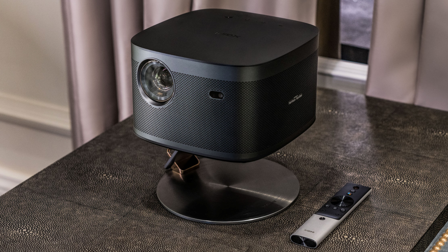
Burgeoning projector specialist Xgimi has launched a pair of flagship portable projectors for the more luxury end of the mini machine market. The Xgimi Horizon and Xgimi Horizon Pro are designed for indoor room-to-room use and mark a new range for this 2013-created company.
The Xgimi Horizon Pro is a 4K HDR model based on the True 4K pixel shifting system which uses a non-4k image sensor to create the 8.3 million distinct pixels required for a 4K picture. It’s bright sounding at 2200 ANSI lumens with an LED light source lifetime that’s rated at 30,000 hours.
That bulb helps make for a fast boot and warm up time with Xgimi quoting just six seconds from button press to maximum operation. You can get an image size anywhere between 40-300in with a throw ratio of 1.2:1.
There’s also a handy AI image-sensing system on board which auto focuses and auto keystone corrects the picture. It’s even intelligent enough to avoid any obstacles such as light switches, plants or vases if projecting onto a wall. There’s a fitting for a tripod screw underneath to make sure you can get your positioning just right.
The 21 x 22 x 14cm body of the Xgimi Horizon Pro has an aluminium frame with a 2 x 8W Harman Kardon speaker system that’s Bluetooth-enabled in case you’d like to stream any audio from a portable device too.
There is little detail on ports so far but there’s wired and wireless networking. Apps are available through the Android TV 10 OS which includes Google Assistant voice control. This won’t guarantee the availability of your favourite streaming services but you will be able to cast content from most missing apps from your mobile or tablet.
The Xgimi Horizon Pro is expected to retail at $1,699 / £1,699 with it planned to launch for pre-order on 10th May.
If that sounds a little strong on the pocket, then the non-Pro variant, the Xgimi Horizon, is just $1,099 / £1,099. It’s almost exactly the same on paper but the resolution maxes out at an SDR 1080p instead. Both projectors can handle 3D content at Full HD. Glasses are not included.
MORE:
Best projectors 2020: Full HD, 4K, portable, short throw
How to set up your projector and get the best picture
Demand for PCs in the second quarter continues to be high amid chip shortages, which constrains manufacturers’ ability to fulfill orders. A new report from Taiwan indicates that some vendors are projected to see shipments fall short of orders by 30% to 50% in Q2 2021.
According to an IDC report, sales of PCs increased by over 55% year-over-year in the first quarter of 2021. Large PC makers have increased their unit sales by well over 50% (with Apple’s shipments increasing by 111.5% YoY). In contrast, smaller makers enjoyed ‘only’ 50% growth, which is explainable as it is easier for large PC makers to procure components that are in short supply due to their volume of scale and buying power.
But apparently, demand for PCs is so high that some notebook makers expect their shipments to fall short of orders by 30% to 50% in the second quarter, according to DigiTimes. Manufacturers naturally prioritize higher-end models, so supplies of inexpensive machines, such as entry-level Chromebooks for education customers, will remain constrained in the second quarter. Meanwhile, 43.8% of Japan’s GIGA School project shipments were Chrome OS-based, followed by Apple MacOS and Microsoft Windows-powered machines.
Taiwanese PC makers now expect supply constraints to persist in the second half of the year as the PC industry has to compete against cars and smartphone producers that also need chips and other components, which will naturally increase the prices of computers.
Interestingly, to secure the supply of hard-to-find components, some vendors even acquire stakes in their suppliers. For example, Acer Group recently invested $53 million in display driver IC supplier FocalTech Systems and now holds a 3.58% stake in the company.
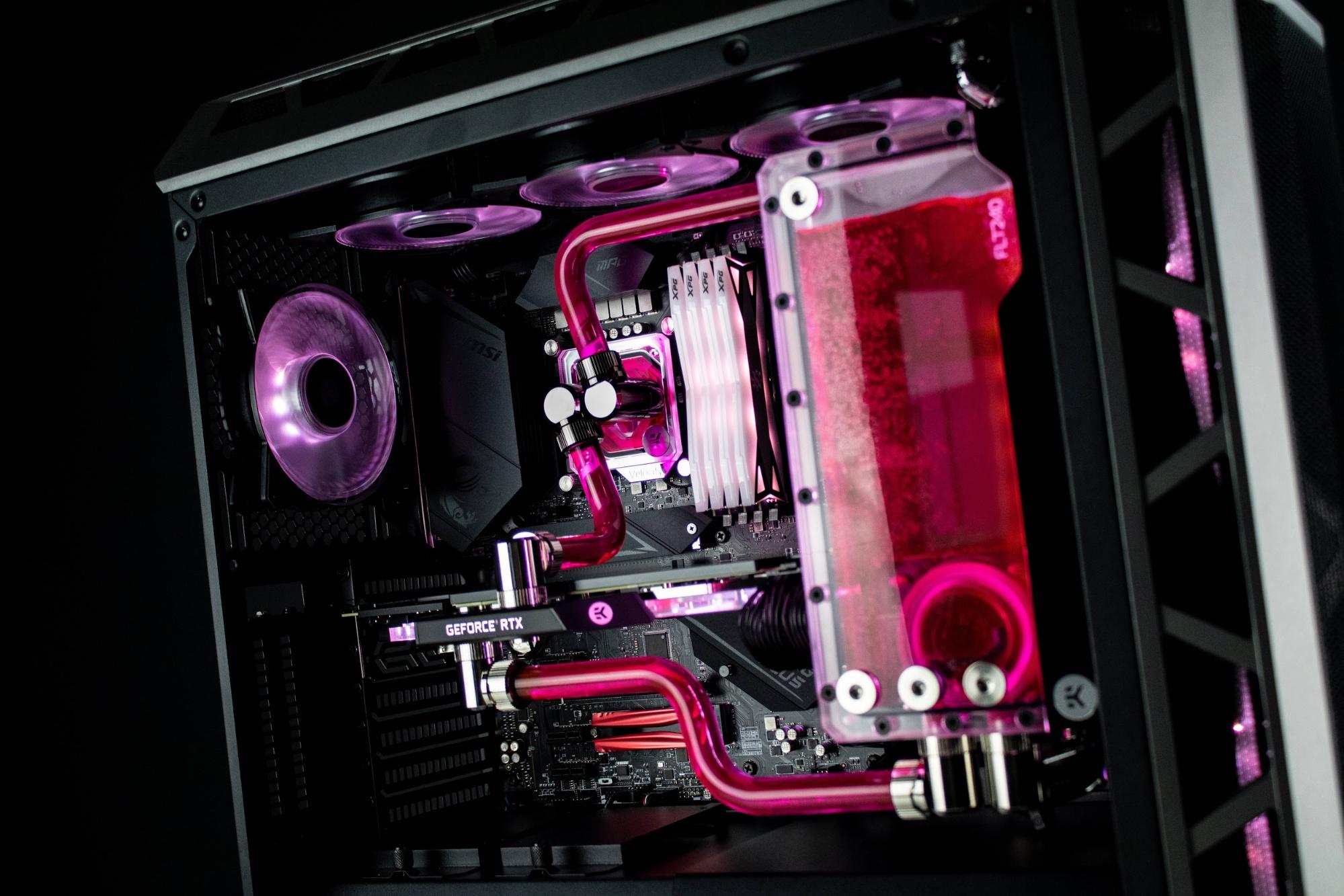
Custom watercooling has always been a popular topic in the enthusiast community, and hard tubing has made it a lot more appealing for people who want cool temps as well as cool looks. It goes without saying that using hard tubing is a real challenge compared to the easier soft tubing approach.
So, in this article, I’m going to show you some of the basics needed to work with hard tubing and the steps I go through when planning an entire hardline custom loop. Let’s get started!
Choosing the Right Tubing
There are a few options available when choosing the type of hard tubing, both for materials and size. The available sizes are 12mm, 13mm, 14mm and 16mm. You should choose based on your tastes in looks, as well as the size of the case, since bigger tubing looks better in bigger cases and vice versa. I have never detected a difference in terms of performance and water flow.
The most common materials are acrylic and PETG, followed by brass, copper, glass and carbon fiber. We will be looking at the first two options here.
So, how do you choose between acrylic and PETG? The main difference is the ease of use: acrylic is more heat-resistant, so it’s a little harder to bend than PETG; acrylic is also harder to cut because you will need some sort of toothed saw, while almost any type of pipe cutter will work on PETG.
That said, I will always recommend choosing acrylic, because a custom loop that runs hot can be enough to warp PETG, causing the tube to pop out of the fitting and casue a disaster. This happened to me in the past with one of my builds. This is what PETG tubing looks like when it deforms under the pressure of the fittings:
(Image credit: Tom’s Hardware)
It’s not super-warped because I replaced it before coolant flooded the case, but the potential for disaster is definitely there. On the other hand, acrylic won’t ever get hot enough to deform, even in the hottest build.
The difference when bending it isn’t even very noticeable. It will just take a little longer to heat the acrylic compared to the PETG. The fact that PETG is softer than acrylic also makes it more prone to give lower-quality bends.
Acrylic is admittedly harder to cut than PETG, but it’s still worth it to have a safer end result. More on the cutting process later.
Some people argue about acrylic being brittle, while PETG is basically indestructible, but that’s only a difference when hammering both. In real scenarios, acrylic tubing will never crack unless you put way too much force on it, which would likely damage other parts of the loop as well, like the threaded ports on acrylic waterblocks.
Acrylic is clearer than PETG, so it also looks slightly better. It actually depends on the various brands and production lines, but this is generally the case. The following photo has 13mm acrylic tubing on the left and 16mm PETG tubing on the right.
(Image credit: Tom’s Hardware)
While soft tubing will only require you to have a pair of scissors at hand, hard tubing is more demanding in terms of needed tools.
The first important tool to have is a silicone insert, which will need to be the same diameter as the inner diameter of the tube. I suggest getting it in the same brand as the tube, since size tolerances often change slightly between brands.
(Image credit: Tom’s Hardware)
A heat gun is needed to bend the tubing, preferably one with different levels of temperature, and some kind of saw together with a deburring tool will serve you well when cutting it to length and cleaning the edges.
(Image credit: Tom’s Hardware)
If you decide to go with PETG, a pipe cutter like the one in the photo will suffice to cut it.
(Image credit: Tom’s Hardware)
If you have access to fancier tools, a scroll saw works great to cut the tubing, and a belt/disc sander to clean up the cut. That’s what I use most of the time.
Image 1 of 2
(Image credit: Tom’s Hardware)
Image 2 of 2
(Image credit: Tom’s Hardware)
There are a few additions you can make to your tool library if you want, like bending and cutting guides such as these ones:
(Image credit: Tom’s Hardware)
They make the job easier for starters, even though I personally don’t use any of these because I find them useless and too fiddly, especially the bending guides.
Bending the Tubes
Wet the silicone insert with soapy water before putting it in the tube; this will make it easier to pull it out after the bend is done.
To mark the spot where the bend needs to be, I draw two marks and set the distance between the two based on the length of tubing I want to bend. So for a standard 90-degree bend I will do about double the diameter of the tube, for example 26mm spacing for 13mm tubing.
(Image credit: Tom’s Hardware)
When doing more exotic bends that are closer to 180 degrees, you will need to heat up a larger area, but it really depends on the specific case or bend, and some trial and error might be needed to get the right result.
Having done that, it’s time to take out the heat gun. Put it on the table facing upwards, and hold the tube above it, constantly turning it and moving it left and right, always staying within the two marks you did.
(Image credit: Tom’s Hardware)
If you did it right, the two marks will be at both ends of the corner radius, or just about there. This will also help you get a wider or tighter radius on the same 90-degreebend, once you get more confident with the process.
(Image credit: Tom’s Hardware)
When do you know the tube is ready to be bent? There are a few signs that can prevent you from wasting a perfectly good piece of tubing. When you bend a tube that’s not hot enough, you will potentially stress the area and cause stretching, which will leave a kink in the inner corner and slightly deform the outer corner, as in the photo:
(Image credit: Tom’s Hardware)
On the other hand, if too much heat is added, the tube will develop bubbles that could potentially be harmful to the integrity of the tube, which is worse than just looking ugly.
(Image credit: Tom’s Hardware)
You know it’s time to go ahead and bend it when it will tend to bend under its own weight, so no force should be needed to shape it. Here’s how a proper bend looks:
(Image credit: Tom’s Hardware)
Compared with the previous one:
(Image credit: Tom’s Hardware)
Cutting the Tubes
Go through the bending process before the cutting one, because it will give you more room for error. A longer tube will be usable when trimmed down to the right length, while a tube that’s too short will be useless.
When I make the bends, I always leave extra length on both ends of the tube, so that I can then go ahead and trim them down.
After having marked the cut, proceed with your preferred method.
(Image credit: Tom’s Hardware)
If adjustment is needed, you can use a rasp or a file.
(Image credit: Tom’s Hardware)
The deburring tool is very useful to clean up the edges and add a small chamfer to the outer edge, which will prevent the o-ring on the fittings from getting damaged. I don’t suggest you use this tool with PETG tubing as it leaves a very rough finish. Instead, just use a file or sandpaper to remove the sharp edges (which kind of defeats the ease of cut with the pipe cutter, but still, just don’t use PETG).
Image 1 of 3
(Image credit: Tom’s Hardware)
Image 2 of 3
(Image credit: Tom’s Hardware)
Image 3 of 3
(Image credit: Tom’s Hardware)
Inserting the Tube in the Fitting
Every fitting has its unique way of holding the tube and securing it. For this guide, I’m using Alphacool Eiszapfen Pro fittings, which have a really strong and secure system, thanks to the big rubber ring.
(Image credit: Tom’s Hardware)
Start by sliding the compression ring together with the rubber ring or o-ring in the tube, then insert it in the fitting, making sure it goes all the way through.
(Image credit: Tom’s Hardware)
Then proceed to put the o-ring/rubber ring in place and tighten the compression ring.
Image 1 of 2
(Image credit: Tom’s Hardware)
Image 2 of 2
(Image credit: Tom’s Hardware)
It’s important to note that during this process, you will need to make sure the tube is as perpendicular to the fitting as possible, because if not, you will most likely scratch the tube while tightening the compression ring. And in extreme cases, this might cause a leak because the seal provided by the o-rings is not even.
(Image credit: Tom’s Hardware)
This should be a good starting point for you to start practicing on your first hardline custom loop. Now let’s see how I usually plan my loops!
Planning the Loop
After having assembled all of the main hardware in the case, I start testing out a few options for positioning the reservoir, which is often the part that needs the most fiddling with. This varies a lot, depending on the type of case and reservoir.
Image 1 of 3
(Image credit: Tom’s Hardware)
Image 2 of 3
(Image credit: Tom’s Hardware)
Image 3 of 3
(Image credit: Tom’s Hardware)
Once I’m happy with the placement of every part, I start playing with fittings to see what kind of setup works best. I always try to usea combination that will allow me to do only one bend on a tube, two at max, because it makes life easier and should look cleaner.
(Image credit: Tom’s Hardware)
The secret to a good-looking tube routing is trying to use the same exact bend radius on all of the tubes in the loop. You can go classic with all 90-degree bends, or you can do something a little more unique like I did in this case, with about 25-degree bends.
(Image credit: Tom’s Hardware)
Taking your time to plan the routing to optimize every tube run will help you get a really professional-looking result. Also, always take into consideration the fact that waterblocks, especially CPU ones (and pumps) have the inlet and outlet specified, so make sure you plan your loop with the right order in mind, otherwise you will get poor performance and poor water flow.
(Image credit: Tom’s Hardware)
Another really fundamental thing in a custom loop with hard tubing is the drain valve, because while you can get away with not using one with soft tubing (because it’s easy to move) hard tubing can’t be moved once it’s in place and full of coolant. So being able to drain the system using a valve will make your life so much easier. Remember to put it at the lowest point in your loop, to help drain as much coolant as possible. In my case, I put it on the bottom-right fitting of the reservoir, so that I could also hide it from sight and maintain a cleaner look.
Filling the Loop
A few years ago, it was perfectly normal to fill your case with paper towels and leak-test the loop by just putting the coolant in and running it for a few hours.
Nowadays we have air leak testers, like the EK one in the photo below. It uses compressed air to find leaks in the loops, although I still find myself just filling the system whenever I detect a leak with the tester, because it’s faster to actually find and fix it.
Remember to run the pump alone with all of the other hardware unplugged, to prevent any damage in case of major leaks.
(Image credit: Tom’s Hardware)
DISCLAIMER: a lot of users are thrown off by the colours in the indicator of this specific tester model. The right pressure to leak-test a full custom loop is around 0.3 bars, so well below the green zone. EKWB is reportedly working on a fix to have clearer indications, although all the info needed is already provided in the manual.
Here’s the build once filled with coolant. Now it’s time to install the OS and RGB software and shoot a few cool photos!
(Image credit: Tom’s Hardware)
Hope you enjoyed this guide, and I hope this will help you with your future endeavors in custom watercooling!
Today, we will be reviewing yet another Xiaomi mid-ranger – we are welcoming the 4G version of the Mi 11 Lite.
We are not sure how Xiaomi can keep uninterrupted production of so many phones with the ongoing global chip shortages. But we are glad things are working well for them so far.
The Mi 11 Lite 5G has already earned our recommendation, and we are hoping its cheaper version to be just as good. The lightweight Mi 11 Lite, just like the Mi 11 Lite 5G, is shaped after the Mi 11 flagship and focuses on similar features – an HRR OLED screen, enjoyable camera quality, long battery life, fast charging, and overall smooth UI experience.
We are glad to see Xiaomi has thoughtfully handpicked the features that matter the most. The 6.55-inch OLED is of great quality with 10-bit color support, HDR10 certification, and a 90Hz refresh rate. There is also 240Hz touch sampling, which is another requirement for a smooth experience.
The triple camera on the back is also reminiscent of the Mi 11’s and the same as on the Mi 11 Lite 5G – there is a high-res 64MP primary, an 8MP ultrawide snapper, and a 5MP telemacro cam. All sorts of shooting modes are supported, including Night Mode, Long Exposure, Pro mode for all cameras, and the Mi 11 series exclusive video modes such as Parallel World, Time Freeze, Night Mode Timelapse, among others.
The Mi 11 Lite relies on the Snapdragon 732G chip – the same one we experienced as part of the Redmi Note 10 Pro. That’s the only notable difference with the Mi 11 Lite 5G – the 5G model uses a more powerful Snapdragon 780G 5G SoC.
The Mi 11 Lite may have undergone an obvious cost-cutting process, but it still gets to enjoy stereo speakers, NFC connectivity, a microSD slot, and even an IR port. And, by looking at its specs sheet, it does seem like a Lite version done right.
Xiaomi Mi 11 Lite specs at a glance:
Body: 160.5×75.7×6.8mm, 157g; Gorilla Glass 5 front, glass back, plastic frame.
Display: 6.55″ AMOLED, 1B colors, HDR10, 90Hz, 240Hz touch sampling, 500 nits (typ), 800 nits, 1080x2400px resolution, 20:9 aspect ratio, 402ppi.
Chipset: Qualcomm SM7150 Snapdragon 732G (8 nm): Octa-core (2×2.3 GHz Kryo 470 Gold & 6×1.8 GHz Kryo 470 Silver); Adreno 618.
Memory: 64GB 6GB RAM, 128GB 6GB RAM, 128GB 8GB RAM; UFS 2.2; microSDXC (uses shared SIM slot).
OS/Software: Android 11, MIUI 12.
Rear camera: Wide (main): 64 MP, f/1.8, 26mm, 1/1.97″, 0.7µm, PDAF; Ultra wide angle: 8 MP, f/2.2, 119˚, 1/4.0″, 1.12µm; Macro: 5 MP, f/2.4, AF.
Front camera: 16 MP, f/2.5, 25mm (wide), 1/3.06″ 1.0µm.
Video capture: Rear camera: 4K@30fps, 1080p@30/60/120fps; gyro-EIS; Front camera: 1080p@30fps, 720p@120fps.
Battery: 4250mAh; Fast charging 33W.
Misc: Fingerprint reader (side-mounted); Infrared port.The most notable omission is splash resistance, obviously. While the similarly priced Poco X3 Pro is IP53-rated, and Samsung is putting an even bigger effort with its most recent IP67-rated Galaxy A phones, Xiaomi isn’t keen on providing any sort of ingress protection for the Mi 11 Lite phones. It’s not a major issue, of course, but it’s already a popular must-have for the competition.
Unboxing the Xiaomi Mi 11 Lite
The Mi 11 Lite bundle is a match to what most of the Redmi and Poco phones recently offered – a 33W power adapter, a 3A-rated USB-C cable, there is also a USB-C-to-3.5mm adapter.
There is also a transparent silicone case inside the retail box – a much-appreciated addition across all Xiaomi phones. Xiaomi is also giving away a thin screen protector, but it’s one of those cheap films that turn your screen into a smudge magnet, and we just couldn’t bear all this smear, sorry.
Home/Software & Gaming/Days Gone PC features and improvements announced, releasing on May 18th
Matthew Wilson 2 days ago Software & Gaming
We’ve known for a while now that Days Gone is the next major PS4 console exclusive to be coming to PC. Now, we have a date and our first look at the PC version in action ahead of launch next month.
Days Gone is coming to PC on the 18th of May on Steam and the Epic Games Store. Similarly to last year’s Horizon Zero Dawn release, Days Gone will support 21:9 ultrawide displays, third-party controllers like the Xbox gamepad, as well as keyboard/mouse with remapping functions.
In the trailer above, we can see the PC version in action, running at 4K and 60 frames per second. The PC version will also include improved graphics over the PS4 version and unlocked frame rates, so you can run it well above 60 frames per second as long as you have the hardware for it. Speaking of hardware, below you will find the minimum and recommended PC specifications for the game:
Minimum:
Requires a 64-bit processor and operating system
OS: Windows 10 64-bit
Processor: Intel Core [email protected] or AMD FX [email protected]
The PC version includes increased level of detail, field of view and foliage draw distance, as well as the usual graphical customisation options we expect to balance fidelity and performance. The Photo Mode is also included for those who enjoy taking impressive screenshots.
Discuss on our Facebook page, HERE.
KitGuru Says: I skipped Days Gone on the PS4 but I’m really looking forward to picking up this PC version. Are any of you planning on grabbing this next month?
Become a Patron!
Check Also
Xbox controller ‘stick drift’ lawsuit will not go to trial
Last year, we learned that Nintendo isn’t the only company facing lawsuits over gaming controller …
We use cookies on our website to give you the most relevant experience. By clicking “Accept”, you consent to the use of ALL the cookies.
This website uses cookies to improve your experience while you navigate through the website. Out of these, the cookies that are categorized as necessary are stored on your browser as they are essential for the working of basic functionalities of the website. We also use third-party cookies that help us analyze and understand how you use this website. These cookies will be stored in your browser only with your consent. You also have the option to opt-out of these cookies. But opting out of some of these cookies may affect your browsing experience.
Necessary cookies are absolutely essential for the website to function properly. This category only includes cookies that ensures basic functionalities and security features of the website. These cookies do not store any personal information.
Any cookies that may not be particularly necessary for the website to function and is used specifically to collect user personal data via analytics, ads, other embedded contents are termed as non-necessary cookies. It is mandatory to procure user consent prior to running these cookies on your website.